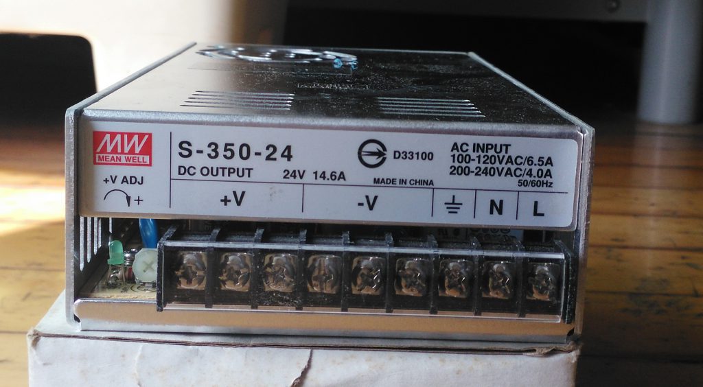
On the side of the Make sure of the input power 110 220V
Connect the wall plug the symbol is ground (green) the N (White) L (black) also Known as Load.
The plastic screw on the left is to adjust the voltage output.
This is a 24 Volts out use a Multimeter and adjust close to your Voltage
| Power is needed on the F4v3 for two purposes:
(1) To power the controller itself (2) To power the pixels which will be attached to the controller. Unlike other Falcon controllers, the power for both the pixels and the controller functionality are powered by a single Power Connector. There is no option for an external power connection on the F4v3.
WARNING: Do not connect the F4v3 directly to a typical
whenever it is being used. Furthermore, if being used outside, a watertight case should be used to protect against the elements. The case needs to allow for air circulation to allow for cooling of the controller during operation. There are many premade cases and do it yourself alternatives for cases and mounting the controller in them, which can be found on the many christmas light forums or group pages. | 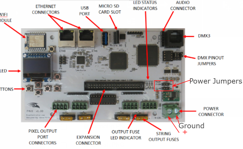
|
| The Input Power Jumpers located on the right side of the board (Figure 2-1), are used to select which voltage, either 5V or 7V to 13V, is being used to power the controller. Both jumpers must be set to the same selection. These jumpers must be set prior to applying power to the controller in order for the board to function and to avoid damage to the controller. The F4v3 is shipped with the jumpers configured for using 12V Power. However, it is always recommended that you check the jumpers before applying power to the controller. WARNING: It is possible to damage your board if you set the jumpers incorrectly! WARNING: Do not remove or install the jumpers while the board is being powered. If using 7V to 13V to power the controller, the Input Power Jumpers must be placed on the left and center pins as shown in Figure 2-3. The F4v3 is shipped with the jumpers in this position. | 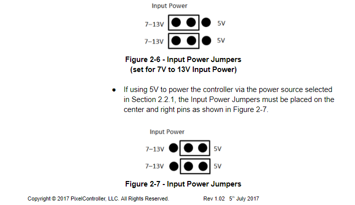 |
|
Power is needed on the F16v3 for two purposes, to power the pixels which will be attached to the controller and to power the controller itself. As most users will select their pixel type and thus voltage prior to setting up the controller, it is covered in the manual first. However, pixels do not need to be attached to the controller to power it up and configure the controller.
WARNING: Do not connect the F16v3 directly to a
Note that since the F16v3 uses power, it should be |

|
|
The F16v3 is shipped with the jumpers configured for using 12V Power on the V2 Power Connector to power the controller. However, it is always recommended that you check the jumpers before applying power to the controller.
WARNING: It is possible to damage your board
|
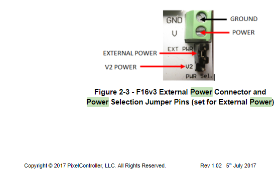 |
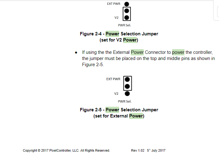
| Power Selection Jumper The Power Selection Jumper located on the right side of the board (Figure 2-1), is used to select which source of power, either the V2 Power Connector or the External Power Connector, will be used for the Controller Power. This must be set prior to applying power to the controller in order for the board to function and to avoid damage to the controller. WARNING: It is possible to damage your board if you set the jumpers incorrectly! WARNING: Do not remove or install the jumpers while the board is being powered.
If using the V2 Power Connector to power the controller, the jumper must be placed on the
|
|
|
Input Power Jumpers
The Input Power Jumpers located near the center of the board (Figure 2-1), are used to select which voltage, either 5V or 7V to 13V, is being used to power the controller. Both jumpers must be set to the same selection. These jumpers must be set prior to applying power to the controller in order for the board to function and to avoid damage to the controller.
WARNING: It is possible to damage your board if you set the
WARNING: Do not remove or install the jumpers while the
which will be running the controller, NOT that which is being output to the pixels. If using 7V to 13V to power the controller via the power source selected in Section 2.2.1, the Input Power Jumpers must be placed on the left and center pins as shown in Figure 2-6. The F16v3 is shipped with the jumpers in this position. |
|
There is an "All" check box and you can test individual ports.
For a better test in Xlights there is a test option under the tool tab.
You can test each model there.